DIGITAL ELECTRONICS
What is DE?
From smartphones to appliances, digital circuits are all around us. This course provides a foundation for students who are interested in electrical engineering, electronics, or circuit design. Students study topics such as combinational and sequential logic and are exposed to circuit design tools used in industry, including logic gates, integrated circuits, and programmable logic devices. (www.pltw.org)
Majority Vote
Description
I had to design a circuit that will allow the four leaders of a company, (President, Vice-President, Secretary, and Treasurer) to vote on decisions and the circuit will give them the outcome of the vote.
Constraints:
Constraints:
- The votes will be Yes (1) or No (0)
- The outcome will be Pass (1) or Fail (0)
- The choice that has the most votes will be the outcome
- In the event of a tie, the outcome will match the President’s vote
Circuit Design
|
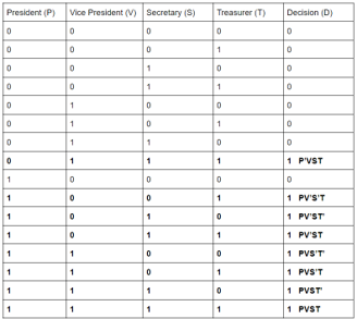
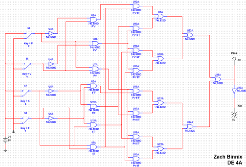
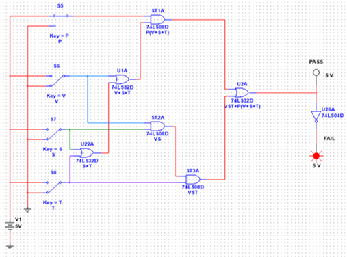
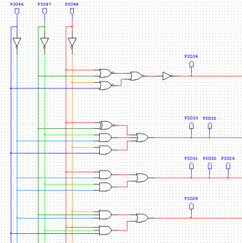
The first step in designing the circuit is claculating all possible input combinations and their resulting outcomes using a truth table. The truth table is used to calculate the logic expresstion, whitch lists all inputs that result in a pass. A process called Boolean Algebra is used to simplify the logic expresstion.
|
|
|
|
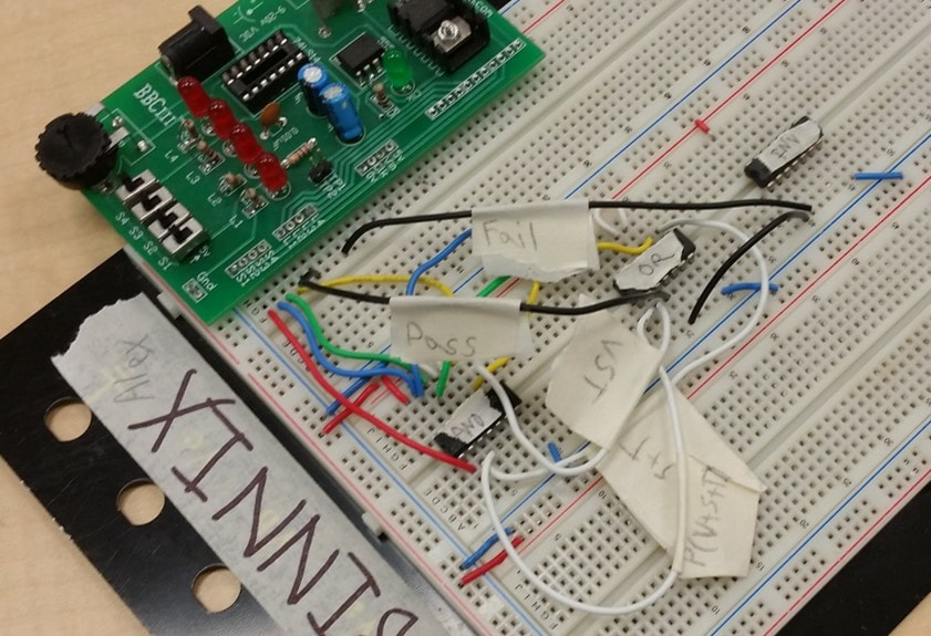
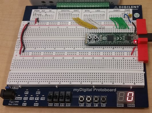
BreadboardingOnce the simple circuit has been designed and tested on a computer, I had to build a physical prototype to test with. I used ‘breadboards’ to make physical, working models of circuits without the need to solder.
|
|
Date of Birth
Description
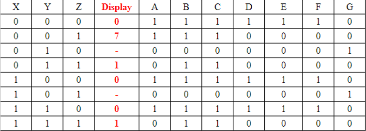
For this project, I had to design a cirucit that will show my date of birth, one digit at a time, on a seven segment display.
Constraints:
Constraints:
- Must have one circuit per segment of the display
- if any of the segments would have the same circuit design, the same circuit may be used for both segments
- Must have two circuits using NAND logic, NOR logic, XOR logic, or XNOR logic gate
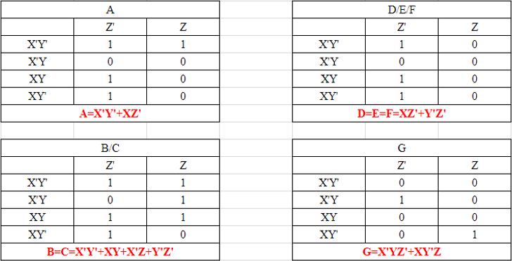
Circuit DesignThe first step was to make a truth table for the circuit. Since all of the segments are controlled by the same inputs, the segments can all be put on the same truth table. I then put the same data into K-Maps. The K-maps show the data differently and allow users to skip the Boolean Algebra.
|
|
|
|
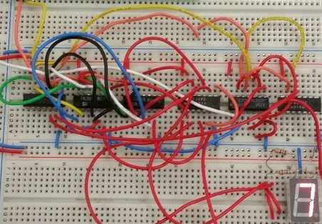
Breadboarding
After desining and testing the circuit on a computer, the circuit is then prototyped using a breadboard.
Programable Logic Device
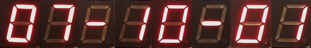
After Breadboarding, I learned how to use a Programable Logic Device (PLD) which allows users to download a circuit without having to physically build the circuit. Once the PLD board is wired and the circuit is downloaded, The circuit is done and ready to test. The outputs read 07-10-01.
|
|
Toll Booth
Description
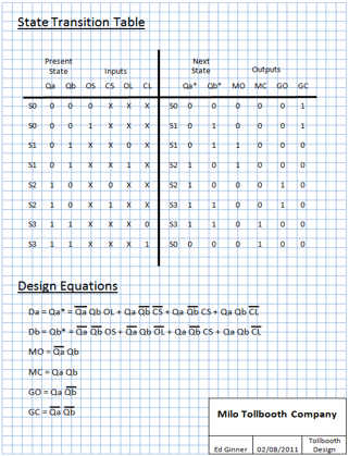
A State Machine is a synchronous, sequential circuit that uses input logic and memory flip-flops to control the output. On each input pulse, the circuit uses the input information and the current state to either move to the next state or stay where it is. Examples include traffic lights, garage door openers, and vending machines. In this project, I designed a circuit that controlled a robotic arm to operate the same as a toll booth.
State Graph and Table
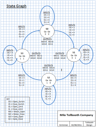
The first step in designing a state machine was to make a state graph. This graph visualized how this particular state machine works and made designing the circuit easier. I then used this data to make a state table. This showed how all of the inputs, states, and outputs interact. For the toll booth, the completed state graph and state table were provided by PLTW.
|
|
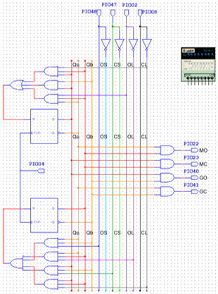
State Machine
After analyzing the state graph and table, I designed the circuit to control the state machine. The PLD was then used to control the robot.
|
|
